Despite starting weeks earlier than usual, Halloween still involved a day of last minute panic to bring everything together. The end result was this:
The basic setup was an update of ideas from previous years and consisted of the following.
3D-printed Mummy in Coffin Doorbell
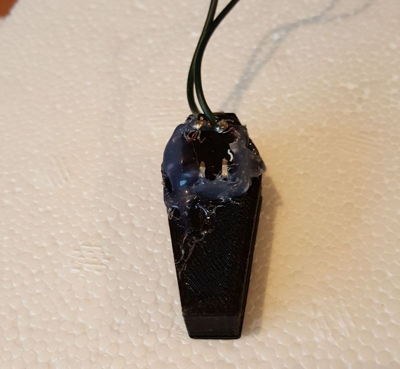
This was my favourite aspect of the whole thing. I spotted a cool 3D design on Thingiverse and realised I could turn it into a doorbell by dremeling a hole in the back and hot-glueing the mummy to a simple push button.
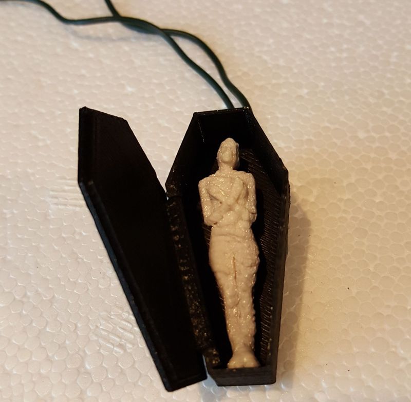
In fact the button was one I originally bought in 2012 when I got back into electronics. There was a small bug in my debounce code which I discovered too late and meant that kids had to press the button twice. But overall only a few failed to figure it out.
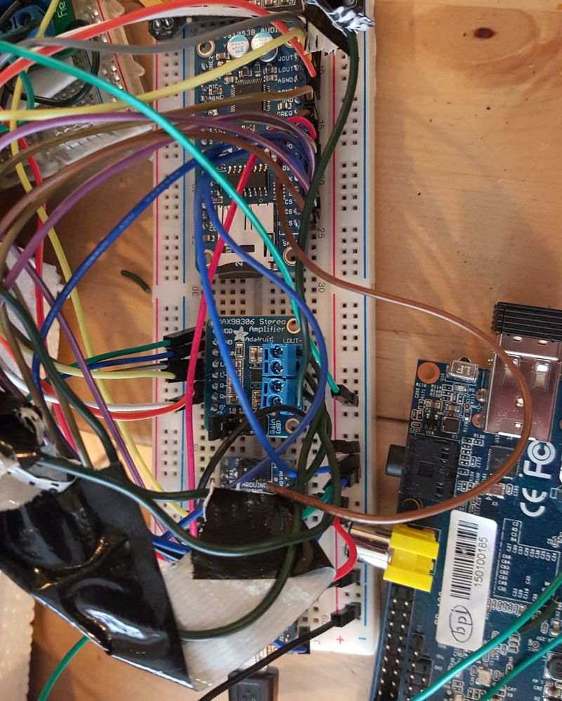
Adafruit Audio breakout board and amp with speakers
I had intended everything to be Arduino and ESP8266 (running Arduino code) only so I needed some way of playing the scream. In previous years I used a Raspberry Pi (successfully) and a really crappy device (less successfully).
In a bizarre twist to the BE Maker Kit Indiegogo scam, one of the people involved somehow got a Florida company to provide free electronics to the right amount. I used this to buy the Adafruit VS1053 Audio board and Adafruit MAX98306 Audio Amp. The wiring on this looks complicated but it’s straight out of their tutorial.
Audio was courtesy of youtube-dl and WinFF on this clip from YouTube.
The Arduino Nano for this was the “Master” device. It detected the doorbell press and then started playing the file on the SD card and sent a high signal both to the Banana Pi for the LED strip and the Arduino Uno for the relays controlling the skull. It’s basically the Adafruit demo VS1053 code with a few extra lines added by me. The code for that is here on Gist.
Wifi Controlled RGB LED Strip using a Banana Pi
I finally ordered a bog-standard 5 metre 5050 RGB LED strip from dx.com over the summer. The value on these things is just staggering at less than €20.
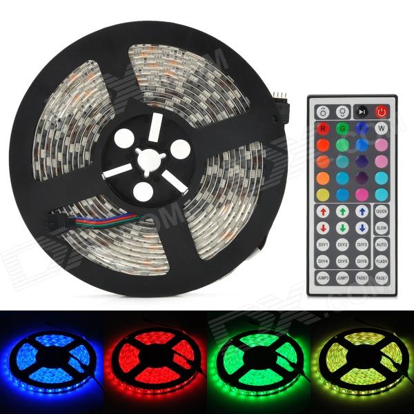
They come with a dedicated remote control and just need a decent PSU to provide the power. Myself and the kids had great fun illuminating my entire home office in a range of colours.
But the challenge for Halloween was how to control it. I could have run irrecord on an ODROID C1 or Banana Pi to reverse engineer the remote control protocol and then use the RC transmitter I bought on DX. But luckily someone told Hackaday about the first ESP8266-powered commercial product they had found. It was a €9 Wifi H801 control module for RGB LED strips! I just had to get one.

It’s a brilliant little box that is easy to wire up and has a simple Android App for control. You connect to the internal Wifi Access Point it provides to do this. Here is the brilliant piece: You then use the app to tell the module to connect to your own Wifi router and then you do the same with the phone. Now your RGB LED strip is on your network!
But it gets better. A very smart person reverse-engineered the basic over-the-air protocol that the app uses to control the Wifi module. Unfortunately he was using a slightly different module to me and it didn’t work. I then spent a week of evenings learning all about Wireshark and Netcat. I was able to do the same as him and find the basic UDP control protocol (only minor difference in the packets)
In summary:
- OFF: \xfb\xeb\x00\x00\x00\x00\x00\x9f\x97\x9d\x00
- RED: \xfb\xeb\xff\x00\x00\x00\x00\x9f\x97\x9d\x00
- GREEN: \xfb\xeb\x00\xff\x00\x00\x00\x9f\x97\x9d\x00
- BLUE: \xfb\xeb\x00\x00\xff\x00\x00\x9f\x97\x9d\x00
My plan was to use a NodeMCU ESP8266 module to send the relevant commands, using either NodeMCU LUA or the Arduino port to ESP8266 but I ran out of time to experiment.
So I had Netcat working happily on the Banana Pi running Fedora but I also needed to be able to use the GPIO pins to tell the BPi when to turn on/off the LED strip. I then made the classic mistake of panicking on Halloween morning and switching to the RaspberryPi so I could use WiringPi for GPIO. Except the Netcat commands hung on the RPi (still no idea why).
Some Googling revealed that WiringPi had been ported to Raspbian on the BPi so I tried that. Same Netcat problem! So I took a chance and re-inserted the Fedora SD card and downloaded the BPi version of WiringPi. Result! It compiled and ran perfectly.
The I moved on to several hours of trying to write a Bash script to monitor a GPIO pin using WiringPi and control the RGB LED strip with echo/netcat. All I will say about that is I am never ever writing a Bash script again (space-sensitive around brackets/equals for the love of god). This is the final result and, to be fair, it worked seamlessly:
#!/bin/bash
sets=`/usr/local/bin/gpio mode 7 down`
setit=$sets
state="low"
echo -e '\xfb\xeb\x00\x00\x00\x00\x00\x9f\x97\x9d\x00' | nc -v -u 192.168.0.128 30977
sleep 1
while :
do
    pins=`/usr/local/bin/gpio read 7`
    if [ $pins = "1" ]; then
        if [ $state = "low" ]; then
            echo -e '\xfb\xeb\xff\x00\x00\x00\x00\x9f\x97\x9d\x00' | nc -v -u 192.168.0.128 30977
            state="high"
            echo high
        fi
    else
        if [ $state = "high" ]; then
           echo -e '\xfb\xeb\x00\x00\x00\x00\x00\x9f\x97\x9d\x00' | nc -v -u 192.168.0.128 30977
           state="low"
           echo low
        fi
    fi
done
But I was so horrified by Bash, I did a quick and dirty re-write to Go this morning. It uses the Golang bindings to WiringPi and seems to work very well.
So the strip was now sorted. On to the rotating skull.
An anatomically correct skull with scary eyes
The skull idea came from a wonderful tested.com video where special effects artist Frank Ippolito bought a cheap skull on Amazon and then used latex, cotton wool and paint to turn it into a horrific burn-victim thing.
I thought we could do the same and found a skull on Amazon UK. It arrived and looked great apart from the lack of a movable jaw. But it then sat there for months with no progress due to me being artistically challenged.
As an alternative I thought about doing something with eyes so I got some half-eyes from Amazon too They were a smidge small but fit for purpose. I grabbed some of my old tiny micro-servos which I have never found a use for and hot-glued the eyes to them. A bit of messing with the range of movement and I had a vaguely spooky setup.
But the fact that you could see the servos and they move pretty slowly meant I was a bit disappointed. I tried to vamp them up a bit more by adding neopixel ring but it was too big so I switched to a single funky Adafruit RGB neopixel on each one. So now I had 6 wires coming out of each eye.
Finally on Saturday morning I went to finish this bit and decided it was too much work to get the Arduino code tweaked to do 2x Neopixels and 2x servos and somehow trigger them on/off on a potentially rotating head. At this point I found the silly fake-eye pingpong balls from last year. A quick cut in the back and I hot-glued a Neopixel to each one. I then hot-glued the eyes into the skull and wired the Neopixels to an Arduino Nano.
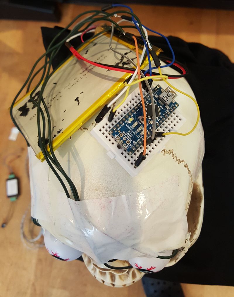
I stuck the Nano and a Lipo battery to the top of the skull and covered it with a cool Buff. Having the eyes on permanently removed a little bit of the element of surprise but I still thought it worked well. The code for the Neopixels was just the standard Adafruit strand test.

Making the skull rotate
I had always known I would rotate the skull in some fashion but for a while I wasn’t sure how. Quite a few weeks ago I came up with the idea to cement a hex driver into the bottom of the skull and sit it on top of a cheap crap €20 electric screwdriver I got ages ago from Woodies.
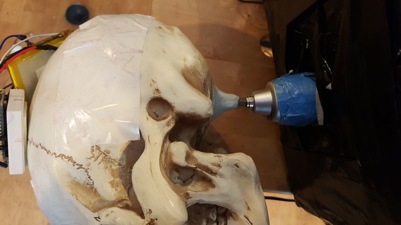
As a screwdriver it was rubbish due to slowness and lack of torque. As a skull-rotator it was awesome, spinning the skull around at high speed.
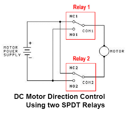
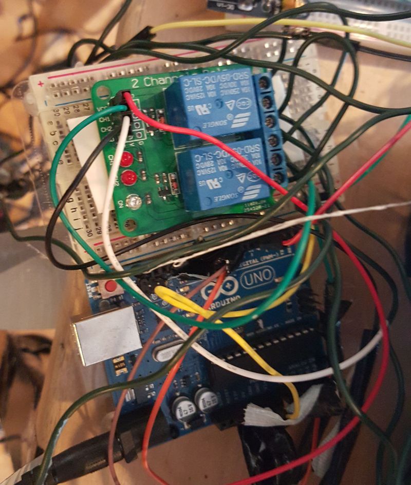
Of course I left the difficult bits until a week before Halloween when I sat down and tried to figure out how to control it all. The first attempt was with a dirt cheap double relay board I got 3 years ago and never used. But I couldn’t figure out how to make it go forwards and reverse. I then tried an old knock-off Adafruit Motor Shield but it couldn’t deliver enough juice (even with a 7.2V LiPo) to overcome the motor’s inertia. Finally I found a relay circuit that did forward/reverse and it worked like a charm.
But how was I going to handle starting/stopping the skull so it was facing away (and potentially covered) initially and then rotating at the right time and stopping in the right position? Of course I left that to Halloween itself.
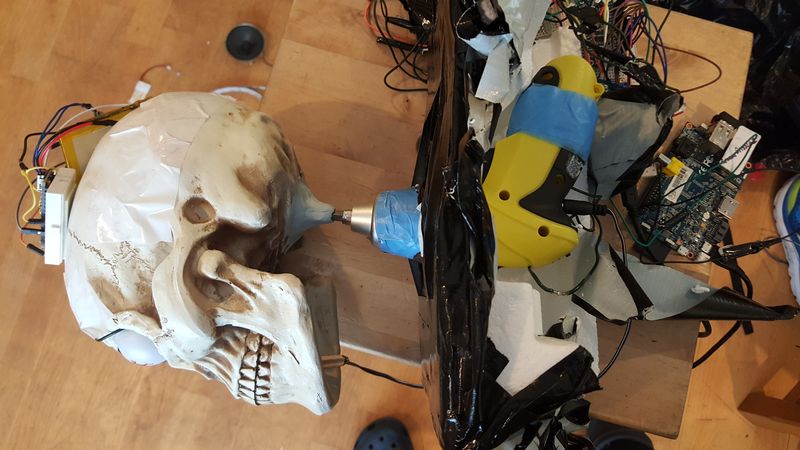
I used polystyrene and duct tape to brace the screwdriver. Then I setup two limit switches. I then applied power. The head spun around and ripped the switches off their mounts. Damn. So another quick executive decision was made. The head would start rotating when the doorbell was pressed and then stop after 10-15 seconds. Which meant some kids would get the full scary effect whilst others would see the flashing eyes before they got to the door.
Tying it all together
This turned out to be pretty easy. I have a ton of decent wire from a dead Christmas tree light string and used that to connect everything up. The doorbell connected to one Arudino which then toggled a pin which the other Arduinos were connected to. After N seconds, it toggled the pin the other way to shut it all down.
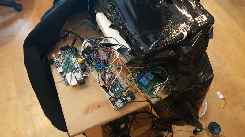
It worked very very well.
Next year?
Hmm not sure. I wanted to do something with ghosts flying down zip wires a few years ago but I just didn’t have the knowhow. I’m feeling a lot more confident about that now.